Wednesday, March 1, 2023

Aircraft Fuel Pumps

Aircraft Fuel Pumps

Aircraft Fuel Pumps - Most manufacturers also provide a means to fuel the aircraft manually using gravity. For this, manual refuel points are located on the wings. In manual refueling, the fueler controls the refueling, and it is recommended to fill up the wing tanks before filling up the center tanks.

The refueling points in most large aircraft can be found under the wings. However, in some aircraft, it is in the side belly. This point is called a refuel coupling, and this is where the fuel bowser hose is connected.

Aircraft Fuel Pumps

Cessna 172Sp Fuel System. Fuel System Failure | By John Debrey | Medium

In addition to the storage tanks, there are tanks present in the fuel system known as surge tanks. These tanks are also a part of the fuel vent system. All the main fuel tanks in the aircraft are connected to the surge tank through a vent pipe. During aircraft maneuvering, any fuel that moves out of the tanks falls into the surge tank through the vent pipe. And when the aircraft levels off, the fuel from the surge tank is gravity-fed back to the main tanks.

The Refueling

The fuel is also used to run the actuators of systems such as the variable stator vanes inside the engines using fuel hydraulic signals. In some aircraft, the fuel is also used to cool the electrical generators.

Once the fuel is pumped by the tank pumps, it is then routed to the Low Pressure (LP) fuel valve, sometimes called the spar valve. From there, the fuel passes through the engine-driven pumps. Some aircraft have both a Low Pressure, LP pump and a High Pressure, HP pump, which is driven by the high-pressure compressor of the engine.
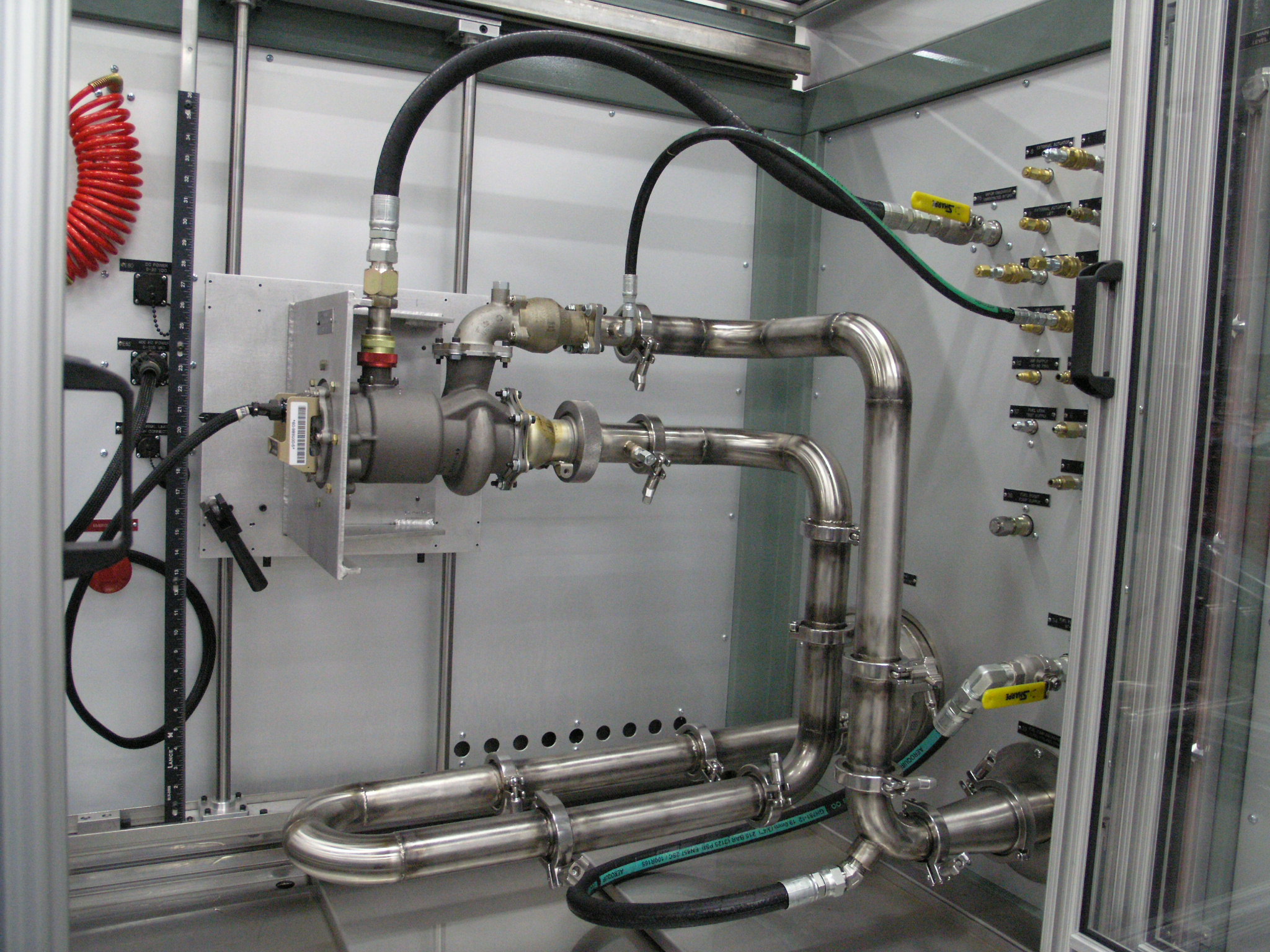
Bauer Model 1734 Universal Fuel Boost Pump Test Stand | Bauer, Inc.

In most large aircraft, the fuel is stored in the wings. Some aircraft also have tanks in the center body, or the center fuselage called center tanks. Widebody aircraft also have tanks in the tail or the horizontal stabilizer which are used to control the center of gravity of the aircraft during long-haul flights.

Our Aircraft Fuel Pumps and Fuel Boost Pump are SFAR 88 Compliant and feature an AC induction motor driven centrifugal pump assembly. Our aviation fuel pump products meet the highest reliability and safety standards for today's modern commercial aircraft.

The Fuel Storage Tanks And Venting System

Wondering what to expect when you trust Aircraft Accessories with your next aircraft fuel pump project? Our talented team of fuel pump specialists will gladly provide you with a custom quote on request. For general questions, or to request a free quote, call or message us today.

The storage of fuel in the wings helps to prevent wing bending stresses. And due to this reason, wing tank fuel is used last during the course of the flight. For example, if an aircraft has a center tank, the center tank fuel is used first before the fuel is drained from the wings. Also, in larger aircraft, the wing tank is divided into an outer and inner tank. In this case, the inner tank fuel is used before the fuel from the outer tank is used. This again helps to relieve stresses on the wing.

Pdf] Temperature And Fluid Property Effects On Cavitation In _ Aircraft  Fuel Pumps | Semantic Scholar

The fuel tanks consist of tank pumps or fuel booster pumps which can be controlled by the pilot. In most cases, each tank has two tank pumps. These pumps are powered by the main electrical system of the aircraft. The job of these pumps is to pump the fuel from the fuel tanks to the main engine-driven fuel pump, which then pumps fuel to the engine itself.

To control the refueling, a control panel is available. In this panel, the operator can dial in or pre-set the amount of fuel that is required. Once the hose is connected, the refuel valves open, and the fueling begins. This entire process is automatic. During refueling, the outer tanks are filled up first. When it is full, fuel overflows into the inner tank and the center tank. When the fuel level reaches the selected value, the refuel valves are closed, and the fueling stops.

Product Description

Weldon Pump is ISO 9001:2015 + AS9100D Aerospace certified for its manufacturing facility in Oakwood Village, Ohio. We are also a Production Approval Holder (PAH – FAA) and all products are manufactured to our FAA approved quality system. The company provides aftermarket support with complete design-build capabilities and testing procedures for aircraft fluid pump systems.

The first three of these factors (voltage, frequency, and plate size) remain fixed, and the only factor that changes is the dielectric constant. This is because, at a given time, the dielectric constant can either be air, fuel, or a mixture of air and fuel. As the capacitor is drenched in fuel, there is an increase in current, which is compared to a reference capacitor with air as a dielectric. The difference in these two measurements can be then used to get a very accurate indication of fuel.

How Aircraft Fuel Systems Work: Cessna 172S | Boldmethod

The crossfeed can also be used to balance the fuel in the air between the tanks. To perform this procedure, the pilots can turn off the wing tank pumps of the lighter side and open the crossfeed valve. This allows the fuller tank to supply both engines. Once the balance between the tanks is achieved, the wing tank pumps can be turned back on and the crossfeed valve closed.

Journalist - An Airbus A320 pilot, Anas has over 4,000 hours of flying experience. He is excited to bring his operational and safety experience to Simple Flying as a member of the writing team. Based in The Maldives.

The Inner Workings Of The Fuel System

A Power Driven positive-displacement rotary-vane pump equipped with a drive for direct coupling with the engine accessory pad or electric motor. As the rotor turns in the eccentric liner the vanes sweep in succession through the space formed by the off-set rotor, creating a suction on the inlet side of pump drawing in fuel. Since fuel is practically incompressible it is forced out through the discharge port by the action of the blades producing pulsation-less flow.

The fuel tank also consists of suction valves that allow fuel to be drawn by the engines in the event of tank pump failure. This requires the pilots to descend to a lower altitude which prevents low-pressure fuel boiling.

Electrically Operated Fuel Pumps | Aircraft Maintenance  Engineering-Mechanical

In aircraft capable of flying at high altitudes, the tank pumps are a necessity because the reduced pressure at altitudes can cause fuel to boil, causing vapor locks that can prevent fuel from entering the engine-driven pump.

In normal operations, the left-wing tank supplies fuel to the left engine, and the right-wing tank supplies fuel to the right engine. In an engine flameout event, the remaining engine can be supplied with fuel from the other side using a crossfeed valve. For example, if the right engine were to fail, fuel from the left-wing tank could be routed to the right engine when the crossfeed valve is opened.

Product Description

The fuel for the Auxiliary Power Unit (APU) is typically fed from one of the wing tanks. It has a pump of its own which automatically comes on when the APU start sequence is initiated. If the APU pump were to malfunction, the supplying tank pumps can be turned on.

To solve this problem, compensators are used. The compensators are probes that are placed deep inside the fuel tanks to ensure that they are always covered in fuel. If there is a reduction in temperature that causes the SG to go up, the compensator increases the current flow to the fuel indicator circuit to correct the erroneous measurement by the fuel-measuring capacitors.

Maserati Mexico, Ghibli, Quattroporte Bendix Style Fuel Pumps | Hardt  Classic Parts

Accepted returns must arrive at our facility within 30 days from invoice issue date with complete paperwork and in original packaging condition or customer will be refused a refund or credit. All items are subject to a 15% restocking fee.

If you will be returning a core, no RMA is required. We recommend sending a copy of your invoice and “Core Return” written in large letters on the bottom. This ensures we know who and what the received shipment is for.

The surge tank is also vented to the atmosphere to release fuel if there is a fuel overflow. It is, at the same time, provided with ram air which helps to pressurize the main fuel tanks. This keeps the tanks at a slight positive pressure. This, for one, prevents excessive fuel evaporation. As the aircraft climbs higher and higher, the reduced atmospheric pressure decreases the boiling point of the fuel. This causes fuel to evaporate. When the tanks are fed with positive pressure, the fuel is kept from experiencing reduced pressure.

Before the fuel is routed to the main engine components, it goes through the fuel/oil heat exchanger and the fuel filter. The heat exchanger keeps the fuel at an optimum temperature, while the filter blocks any debris in the fuel. Once passed through the exchanger and the filter, the fuel is pumped by the HP pump to the fuel nozzles in the combustion chamber.

The main problem with this system is that it cannot compensate for the temperature. The Specific Gravity (SG) or density of the fuel is inversely proportional to the temperature. Thus, when there is a drop in temperature, the fuel volume reduces and causes errors in fuel indication. Similarly, when there is an increase in the temperature, the fuel volume increases.

Our Aircraft Fuel Pumps and Fuel Boost Pump are SFAR 88 Compliant and feature an AC induction motor driven centrifugal pump assembly. Our aviation fuel pump products meet the highest reliability and safety standards for today's modern commercial aircraft.

aircraft electric fuel pump, weldon fuel pumps aircraft, aircraft fuel pump repair, engine driven pump aircraft, aircraft fuel pump overhaul, engine driven fuel pump aircraft, aircraft fuel boost pump, jet engine fuel pump

Aircraft Fuel Gauge

Aircraft Fuel Gauge

Aircraft Fuel Gauge - 7. Because the engine moves and vibrates on shock mounts, a flexible fuel hose, such as an Aeroquip 303-6, must be used for the fuel line between the gascolator and the carburetor. Its minimum inside diameter is 3/8" and its size is identified as a -6.

Hot weather combined with high engine compartment temperatures can be conducive to the formation of vapor lock in the fuel lines. You can minimize the risk of vapor lock taking place in your fuel system by:

Aircraft Fuel Gauge

Ww2 German, Soviet, Allied Militaria, Uniforms, Awards, Weapons History.  War Relics Forum

Fuel Starvation Fuel starvation, at the very least, means a forced landing or, worse, a crash landing which may or may not be fatal. There are a number of causes for this problem. The most mortifying being that the pilot simply allows the engine to run out of fuel.

Fuel Selector Valve

Please feel free to call our sales department at +1-714-705-4780, Our knowledgeable sales staff is available 7 days a week, 18 hours a day, from 5:00 AM PST to 12 AM PST or email your requirements to sales@completesourcingsolutions.com

So, who or what is to blame? Believe it or not, sometimes the fuel system installation or the design of the individual component parts may trick the pilot into jumping to the wrong conclusion or taking the wrong corrective action.

Here are the most frequently cited causes for fuel starvation: This is an important component for these aircraft fuel systems. According to the Aircraft Owners and Pilots Association (AOPA), the fuel selector valve "allows the pilot to choose which tank is feeding fuel to the engine.

Some systems require you to alternate between Left and Right tanks, while others offer a Both position. Some aircraft might favor one side over the other when Both is selected; select the appropriate side to rectify any fuel imbalance.

Ep. 57: Airplane Instruments | Gauges | Dials | All Explained - Youtube

Fuel Pressure Gauge

The selector also has an Off position.” "We Proudly Support Intrepid Fallen Heroes Fund that serves United States Military Personnel experiencing the Invisible Wounds of War: Traumatic Brain Injury (TBI) and Post Traumatic Stress (PTS). Please visit website (www.fallenheroesfund.org) and help in their valiant effort".

If fuel pumps are installed within the fuel system, a fuel pressure gauge may also be provided. This gauge measures the pressure within the fuel lines. The normal operating pressure can be found in the AFM/POH or on the gauge by color coding.

As the temperature in the tank changes, the density and hence volume of the fuel will also change. Therefore, a vented tank is a good idea because it allows fuel to escape if expansion has occurred at elevated temperatures.

Regulatory requirements specify that the system must allow flow rates to exceed 150 percent of the takeoff fuel consumption for the aircraft engine. Occasionally booster pumps are also used as a means for increasing gravity fed systems – typically for engines with fuel injection instead of carburetor-based systems.

Fuel Pump System

It's True Finally, if the engine quits, immediately switch to the other tank. . . if you have one. A logical procedure, if you stay calm, cool and collected, isn't it? Maybe that tank has fuel and/or its vent is not plugged.

Low-wing airplanes with tanks installed in their wings need pumps to transport the fuel from the tanks to the carburetor or injectors. A system dependent for pumps feeding the engines needs a minimum amount of redundant power achieved by using two fuel pumps, one driven by the main engine and one electrically driven.

Dreaded Fuel Gauge Repair - Vintage Mooneys (Pre-J Models) -  Mooneyspace.com - A Community For Mooney Aircraft Owners And Enthusiasts

The electric auxiliary fuel pump operates from an electrical switch inside the cockpit. Most fuel systems in homebuilts have been surprisingly trouble-free. For the most part, more so than some builder-pilots. Mechanical and fuel management problems do, of course, crop up, but no more frequently than they do in commercially produced certified aircraft.

After leaving the fuel tank, and before reaching the carburetor or injector, the fuel passes through a fuel strainer to get rid of any moisture in the system. These pollutants are heavier than fuel for aircraft so they settle in sumps at the bottom of a strainer.

Fuel Strainers And Sumps

Depending on fuel type and location, the fuel pump may include a drain pipe or outlet. Both gravity feeding and pumped fuel systems can include fuel primers. The fuel primer can be used for injecting gasoline directly into the cylinder before launching the vehicle.

In the cold weather when engines find difficulties while starting, fuel primers help as long as the fuel is not frozen. I attribute this success mostly to the technical guidance made generally available by the EAA for more than 40 years through its publications, forums, Technical Counselors, and the free exchange of information among member homebuilders themselves.

If your fuel system has been reliable and trouble-free, don't be too quick to change it unless you understand the need for doing so. . . after all, it could be that your way is better than those I'll be describing.

Moreover, it is vital that fuel tanks remain sealed at all times to avoid any external contamination to reach the fuel system, including dirt, dust, and water. There are some tasks that an aircraft fueler is usually responsible for.

Fuel Gauges Non-Functional In V4 - Prepar3d Forums

Fuel Primer

Would it surprise you, however, to learn that there have been pilots who have experienced engine failure due to fuel starvation, made a forced landing, or a crash landing, only to be informed later by the FAA that they found evidence that the other tank

still had fuel at the time of the incident? Instead, installation could be done by deflating the tank and folding or rolling it to its minimum expression, placing the bladder through a check hole, and unfolding it in the desired place.

During installation, the personnel must guarantee there are no wrinkles to avoid contamination from entering the tank. 2. Each fuel tank must be vented, otherwise the fuel will not flow. Usually some attempt is made to increase the head pressure on the fuel.

For example, a curved tube facing the slipstream is sometimes soldered to the filler cap. This type of installation can be risky if the cap is improperly installed with the tube facing backwards. A better arrangement is to run the vent line from the fuel tank to some point below the fuselage.

Some Final Words

Its outlet opening, too, faces forward to take advantage of the ram air effect. The ram air, in effect, increases the fuel head pressure and helps gravity move the fuel to the carburetor. Not too many years ago, this sort of information was quite scarce and the average homebuilder had to do his own research, and figure out for himself what he needed to install a functional fuel system.

Each tank has a drain installed below to allow all sediments and water to be safely drained from the tanks together with any fuel remaining. Also, because fuel is not pumped from the bottom of the tank but from higher levels, it is the bottom of the tank where the fuel is more susceptible to contamination.

Douglas C-47 Skytrain Ea48-5-24 4 X Tank Fuel Indicator | Recovery Curios

This explains why certain amounts of fuel in the tank are always considered unusable; therefore, aircraft manufacturers provide the usable fuel capacity compared to the total fuel capacity. He had to worry about what size fuel lines to install, about vented and non-vented fuel caps, about where and how to install fuel filters, and lots of other details that have since become common knowledge in homebuilder circles.

Tanks must be isolated from, and cleared of personnel compartments by a smoke and fire-proof enclosure. It is important that tanks remain ventilated at all times so that no accumulation of dangerous fumes or vapors occurs while in the air or on the ground.

Fuel Tanks

6. The gascolator is the second fuel strainer in the system. Its screen is finer than that of the finger screen (about 60 mesh/in.) and its job is to screen out smaller particles which may escape past the finger screen.

Any water in the fuel will also settle to this point. The gascolator is mounted on the firewall in the lowest part of the fuel system, if possible, and should be fitted with a quick drain valve.

5. The rigid fuel line between the fuel tank and firewall is made of 5052-0 aluminum tubing and should be fitted with flared AN fittings. The minimum acceptable outside tubing diameter is 3/8". The fuel line will run downstream from the fuel tank shut-off valve to the gascolator.

Fuel pump systems are the ones used in more complex aircraft with low-wing designs, and they are more suitable when using integral tanks. Yet, the other two types of tanks can also be used with a fuel pump system.

Fuel Indicating Systems | Quiet Wing Corporation

Bladder Fuel Tank

As you know now, the engine fuel system of an aircraft is simpler than many people imagine, especially when it comes to light aircraft with a single engine. Obviously, the bigger the airplane the more necessary fuel pumps become to make sure the flow is steady as required for proper operation.

Large transport category aircraft use Fuel Quantity Management Systems which make use of capacitive measuring systems. Basically a system which can sense the fuel quantity using the electric capacitance of air and fuel as a means to sense how much fuel is inside a tank.

These tend to be considerably more accurate than mechanical gauges. The first component in an aircraft fuel system is the fuel tank. Aircraft fuel tanks are critical components of fuel systems since they store a flammable fluid while being exposed to vibration, aerodynamic forces, heat, cold, inertial loads, and even lightning strikes during flights.

1. The fuel tank(s) in a gravity flow fuel system must be at a higher level than the carburetor to ensure adequate fuel flow. It is an ideal system for high wing aircraft but just about automatically rules out low wing aircraft with wing tanks.

Gravity Feed Fuel System

The indicator must be calibrated to read zero when that tank is actually empty of all usable fuel (in level flight). Bouncing is fine as long as they don't bounce when the tank is actually empty.

This website uses cookies so that we can provide you with the best user experience possible. Cookie information is stored in your browser and performs functions such as recognizing you when you return to our website and helping our team to understand which sections of the website you find most interesting and useful.

Of course, there are many more details behind the operation of a fuel system, and they will vary widely from one aircraft to another. Yet, we will do our best to describe the most critical aspects of fuel systems found in different types of aircraft, so keep reading to find them out.

Tank Ventilation

experimental aircraft fuel gauge, mechanical fuel level gauge, fuel flow gauge aircraft, fuel gauges for tanks, aircraft fuel pressure gauge, mechanical fuel gauge, aircraft fuel gauge repair, fuel indicator

Aircraft Ground Deicing

Aircraft Ground Deicing

Aircraft Ground Deicing - Failure to remove contamination from an airframe and/or to protect it from acquiring further contamination before it becomes airborne may result in sudden loss of control at or shortly after take off. In the case of aircraft with rear mounted engines, any ice on the inner wings of an aircraft at take off may be shed and ingested into the engines causing a partial or total loss of thrust.

On 13 December 2017, control of an ATR 42-300 was lost just after it became airborne at night from Fond-du-Lac and it was destroyed by the subsequent terrain impact. Ten occupants sustained serious injuries from which one later died and all others sustained minor injuries.

Aircraft Ground Deicing

Pdf) Impinging Spray Technique For Ground Deicing The Aircraft Icing  Conditions

The Investigation found that the accident was primarily attributable to pre-takeoff ice contamination of the airframe with an inappropriate pilot response then preventing an achievable recovery. It was found that significant airframe ice accretion had gone undetected during an inadequate pre-flight inspection and that there was a more widespread failure to recognize airframe icing risk.

Additional Issues

It should be noted that fan blade ice which may be accumulated after the pre-start visual inspection, including while the engines are running at low thrust prior to take off, is removed by following prescribed engine handling procedures.

Note: Although the Association of European Airlines (AEA) ceased to exist in 2016, the most recent of their publications still contain some relevant information. Readers are cautioned to validate the recommendations of these guidebooks using more current information sources.

Secure .gov websites use HTTPS A lock ( LockA locked padlock ) or https:// means you've safely connected to the .gov website. Share sensitive information only on official, secure websites. On January 13, 1982, an Air Florida Boeing 737-200 took off in daylight from runway 36 at Washington National in moderate snow but then stalled before hitting a bridge and vehicles and continuing into the river below after just one minute of flight killing most of the

occupants and some people on the ground. The accident was attributed entirely to a combination of the actions and inactions of the crew in relation to the prevailing adverse weather conditions and, crucially, to the failure to select engine anti ice on which led to over reading of actual engine thrust.

On 26 December 2007, the crew of a Bombardier Challenger 604 which had received a 2-stage ground de/anti icing treatment lost roll control as the aircraft got airborne from a snow-covered runway at Almaty in freezing mist and light snow conditions and it

Ground Icing: De-Icing Operations - Fluid Application Procedures

crashed within the airport perimeter before continuing through the perimeter fence and catching fire. The Investigation concluded that the loss of control was probably caused by contamination of the wing leading edge with frozen deposits during the take off roll as a result of the crew's decision not to select wing anti-ice contrary to applicable procedures.

On January 31, 2005, the pilot of a Cessna 208 which had just taken off from Helsinki lost control of their aircraft as the flaps were retracted and the aircraft stalled, rolled to the right and crashed within the airport perimeter.

The Investigation found that the take off had been made without prior airframe de/anti icing and that accumulated ice and snow on the upper wing surfaces had led to airflow separation and the stall, a condition which the pilot had failed to recognize or respond appropriately to

for undetermined reasons. In respect of engines, frozen deposits within the intakes including on the fan blades of jet engines may detach and be ingested by the same engine(s) during the subsequent application of take off power, with the attendant risk of adverse effects on engine performance during

the potentially critical stage of initial climb, including the possibility of engine flameout. On 2 April 2012, the crew of an ATR72-200 which had just taken off from Tyumen lost control of their aircraft when it stalled after the flaps were retracted and did not recover before it crashed and caught fire killing or seriously injuring all occupants.

The Investigation found that the Captain knew that frozen deposits had accumulated on the airframe but appeared to have been unaware of the danger of not having the airframe de-iced. It was also found that the crew had not recognized the stall when it occurred and had overpowered the stick pusher and pitched up.

On 13 January 2016 ice was found on the upper and lower wing surfaces of a Boeing 777-300ER about to depart in the late morning from Lisbon in CAVOK conditions and 10°C. As Lisbon had no de-ice facilities, it was towed to a location where the sun would melt the ice more quickly but during poorly-planned manoeuvring, one of the wingtips was damaged by contact with an obstruction.

Aircraft Ground Support Applications | Process Air Solutions

The Investigation attributed the ice which led to the problematic re-positioning to the operator's policy of tanking most of the return fuel on the overnight inbound flight where it had become cold-soaked. On 4 March 2019, a Boeing 767-300 crew lost directional control of their aircraft as speed reduced following their touchdown at Halifax and were unable to prevent it being rotated 180° on the icy surface before coming to a stop facing the runway landing threshold.

The Investigation found that the management of the runway safety risk by the airport authority had been systemically inadequate and that the communication of what was known by ATC about the runway surface condition had been incomplete.

A number of subsequent corrective actions taken by the airport authority were noted. On 12 March 2005, the crew of a BAe 146-300 climbing out of Frankfurt lost elevator control authority and an un-commanded descent at up to 4500 fpm in a nose high pitch attitude occurred before descent was arrested and control regained.

After landing using elevator trim to control pitch, significant amounts of de/anti-icing fluid residues were found frozen in the elevator/stabilizer and aileron/rudder gaps. The Investigation confirmed that an accumulation of hygroscopic polymer residues from successive applications of thickened de/anti ice fluid had expanded by re-hydration and then expanded further by freezing thus obstructing the flight controls.

First of all, the aircraft must be inspected for signs of contaminant already adhering to surfaces and where found on surfaces which must be free of contaminant, it must be removed using a suitable ground de-icing fluid.

On January 17, 2004 a Cessna 208 Caravan operated by Georgian Express, took off from Pellee Island, Ontario, Canada, at a weight significantly greater than the maximum allowed and with ice visible on the airframe. Shortly after take off, the pilot lost control of the aircraft and it crashed into a frozen lake.

On 11 January 2017, control of a Cessna Citation 560 departing Oslo on a short positioning flight was lost control during flap retraction when a violent nose-down maneuver occurred. The First Officer took control when the Captain did not react and recovered with a 6 g pullout which left only 170 feet of ground clearance.

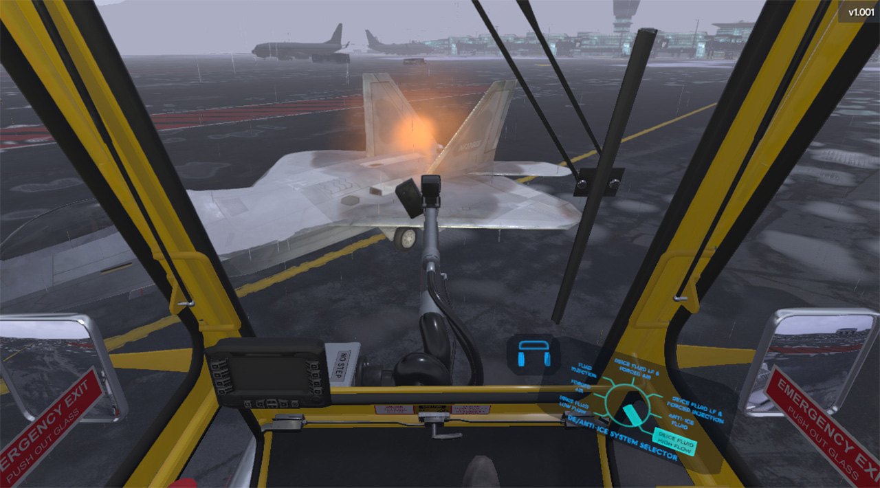
Aircraft Deicing Operator Training Simulator - Forgefx Simulations

A MAYDAY - subsequently canceled when control was regained - was declared and the intended flight was then completed without further incident. The Investigation concluded that tailplane stall after the aircraft was not de-iced prior to departure was the probable cause of the upset.

Use of thickened Type 2 and Type 4 ground de/anti icing fluids has sometimes resulted in fluid residues accumulating in aerodynamically quiet areas of the external airframe structure, particularly in the gap between the leading edge of the elevator and the horizontal stabilizer and also in the

gap between the leading edge of the ailerons and the wing structure. When this residue is subsequently re-hydrated and then exposed to sub zero temperatures in flight, it freezes and can then result in primary flight control restrictions on aircraft types such as the BAE 146/Avro RJ series and the DC9/MD 80/90 series

which have at least some unpowered flight controls. After a number of Serious Incident Reports, many Operators of affected aircraft types have adapted their aircraft maintenance procedures to carry out appropriate inspections and residue removal when these fluids have been applied.

Secondly, the prevailing weather conditions must be assessed. If further adherence of contaminant to the airframe surfaces is currently occurring or anticipated prior to the time at which it is expected that the aircraft will get airborne, then a suitable ground anti-icing fluid should be applied.

In both cases, the time after the start of fluid treatment from which protection is provided by the fluids applied depends upon the prevailing conditions. The fluids are designed to shear off the aircraft surfaces to which they have been applied no later than the point at which the aircraft becomes airborne.

This means that the ground application of fluids has no effect on the risks which arise from the accretion of frozen deposits on the aircraft at any time after take off. On 9 April 2008, a BAe Jetstream 41 departed Aberdeen in snow and freezing conditions after the Captain had elected not to have the airframe de/anti iced having noted the delay this would incur.

Aircraft De-Icing And Anti-Icing Protection For Aircraft And Runways

During the climb in IMC, pitch control became problematic and an emergency was declared. Full control was subsequently regained in warmer air. The Investigation concluded that it was highly likely that prior to take off, slush and/or ice had been present on the horizontal tail surfaces and that, as the aircraft entered colder air at altitude, this contamination had restricted the mechanical pitch control.

On 4 January 2002, a Bombardier Challenger 604 became very quickly uncontrollable as the crew attempted to rotate for lift off at Birmingham and within a few seconds it had crashed inverted near the airport passenger terminal killing all on board.

A rigorous investigation found that an uncontrollable roll had occurred after an aerodynamic stall attributable to frost on the wings which had been noticed but apparently not considered indicative of a need for de-icing. The exclusively FAA promoted notion of polished frost may have played a part in the pilots decision making and was considered to be dangerously misleading.

On 7 November 2016, severe airframe vibrations occurred to an Avro RJ-100 which, following ground de icing, was accelerating in the climb a few minutes after departing from Gothenburg. The crew were able to stop the vibrations by reducing speed but they declared an emergency and returned to land where significant quantities of ice were found and considered to have been the cause of the vibrations.

The Investigation concluded that the failure of the de-icing operation in this case had multiple origins which were unlikely to be location specific and generic safety recommendations were therefore made. On 4 March 2013, a Beechcraft Premier 1A stalled and crashed soon after taking off from Annemasse.

The Investigation concluded that the loss of control was attributable to taking off with frozen deposits on the wings which the professional pilot flying the privately-operated aircraft had either not been aware of or had considered insignificant.

It was found that the aircraft had been parked outside overnight and that overnight conditions, particularly the presence of a substantial quantity of cold-soaked fuel, had been conducive to the formation of frost and that no airframe de/anti icing facilities had been available at

Pdf) Numerical Simulation And Experimental Validation Of Aircraft Ground  Deicing Model

Annemasse On 4 March 2016, the flight crew of an ATR72-500 decided to depart from Manchester without prior ground de/anti icing treatment judging it unnecessary despite the presence of frozen deposits on the airframe and from rotation onwards found that manual forward control column input beyond

trim capability was necessary to maintain controlled flight. The aircraft was subsequently diverted. The Investigation found that the problem had been attributable to ice contamination on the upper surface of the horizontal tailplane. It was considered that the awareness of both pilots of the risk of airframe icing had been inadequate.

On 04 November 2003, the crew of a de Havilland DHC-8-100 which had been de/anti iced detected a pitch control restriction as rotation was attempted during take off from Ottawa and successfully rejected the take off from above V1.

The Investigation concluded that the restriction was likely to have been the result of a remnant of clear ice migrating into the gap between one of the elevators and its shroud when the elevator was moved trailing edge up during control checks and observed that detection of such clear ice

remnants on a critical surface wet with de-icing fluid was difficult. On 27 December 1991, an MD-81 took off after airframe ground de/anti icing treatment but soon afterwards both engines began surging and both then failed.

A successful crash landing with no fatalities was achieved four minutes after take off after the aircraft emerged from cloud approximately 900 feet above terrain. There was no post-crash fire. The Investigation found that undetected clear ice on the upper wing surfaces had been ingested into both engines during rotation and initiated engine surging.

Without awareness of the aircraft's automated thrust increase system, the pilot response did not control the surging and both engines failed. Please note, Aircraft Spruce's personnel are not certified aircraft mechanics and can only provide general support and ideas, which should not be relied upon or implemented in lieu of consulting an A&P or other qualified technician.

Aircraft Spruce assumes no responsibility or liability for any issue or problem which may arise from any repair, modification or other work done from this knowledge base. Any product eligibility information provided here is based on general application guides and we recommend always referring to your specific aircraft parts manual, the parts manufacturer or consulting with a qualified mechanic.

On 28 November 2004, the crew of a Bombardier Challenger 601 lost control of their aircraft soon after getting airborne from Montrose and it crashed and caught fire killing three occupants and seriously injuring the other three.

The Investigation found that the loss of control had been the result of a stall caused by frozen deposits on the upper wing surfaces after the crew had failed to ensure that the wings were clean or use the available ground de/anti ice service.

It was concluded that the pilots' lack of experience of winter weather operations had contributed to their actions/inactions. Toll Free: 877-477-7823 Customer Service: 800-861-3192 Fax: 800-329-3020

aircraft deicing fluids, type 1 aircraft deicing fluid, aircraft deicing types, aircraft deicing equipment, aircraft deicing companies, aircraft deicing boots, aircraft deicing equipment manufacturers, de icing aircraft